|
|
|

| |
|
| Assembly of NARAM Shuttle |
|
 ET components: back - Vac-formed nose and fiberglass (Jay Marsh) main tube center - Removeable Engine mount assembly front - Aft bulkhead, vac-formed aft dome, Intertank bulkhead |
 Intertank Bulkhead: Servo in center drives SRB attachment latches. Hole near top/back is for engine mount assembly, threaded nylon bolts and cast red thumbnuts help secure removeable engine mount assembly. Holes near front are lightening holes and provide good access and views inside of main ET. |
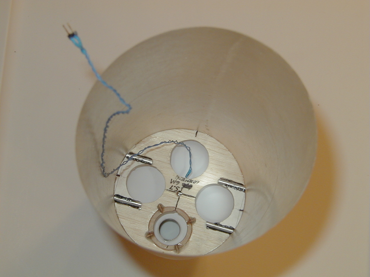
 Aft Bulkhead: Hole near top/back is for lower portion of removeable engine mount assembly. Four wedges help to guide the engine mount into place. To left and right are four pieces of 5/32" aluminum tubing, into which the 1/8" diameter SRB aft attachment rods will be secured. |
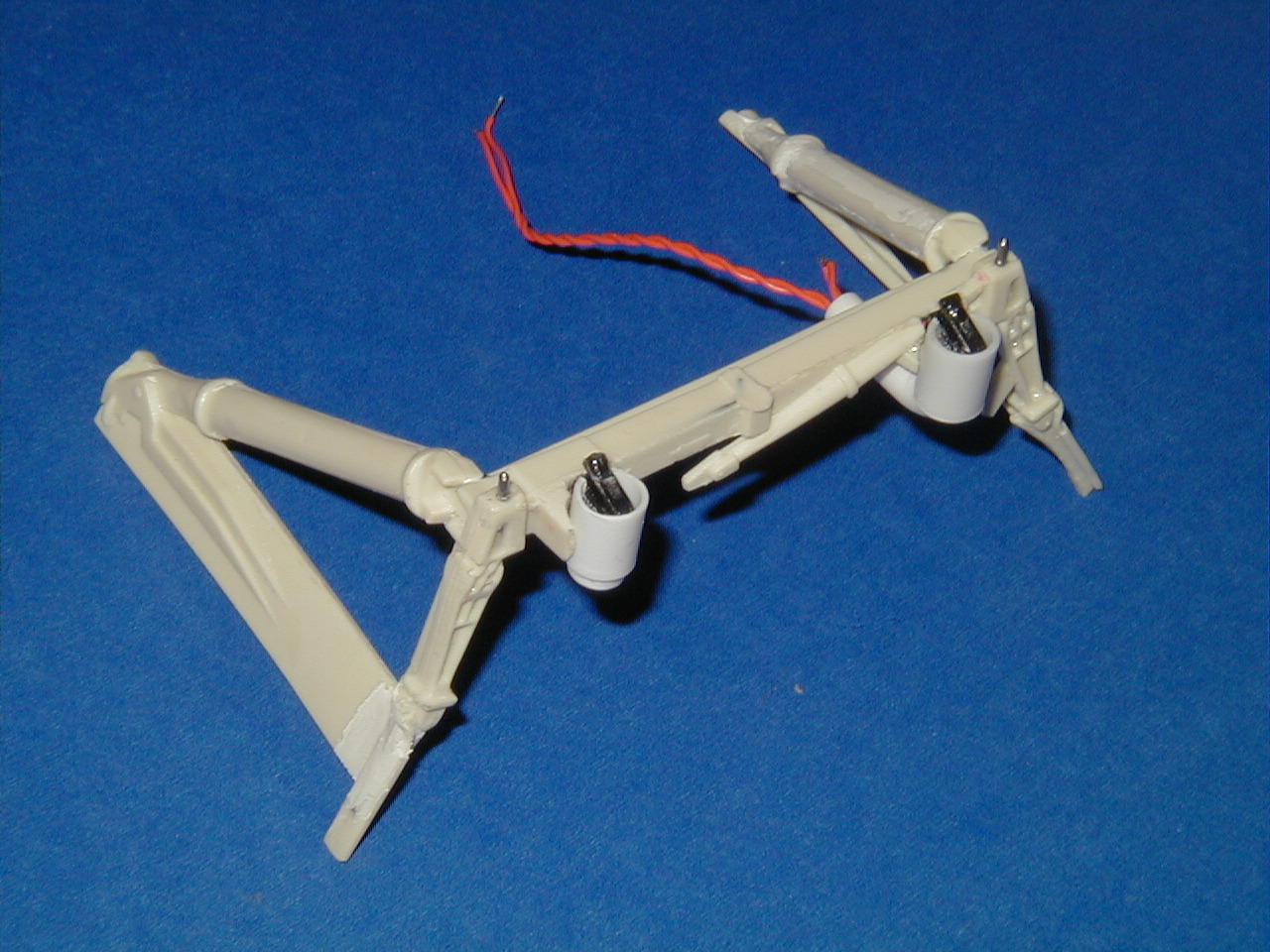
 Removeable Engine Mount: Engine is free to slide 1/8" against a thrust sensor assembly. Fiberglass tube by Ross Hironaka |  Thrust Sensor: Small Lever switch as sensor. Pen springs mounted inside to help push engine back after thrust drops too low, via 3/32" plastic tubing. |
|
|
 Aft Bulkhead after gluing to ET. Also seen is liftoff sensor lead wiring. |
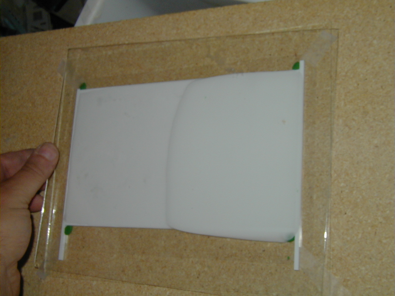
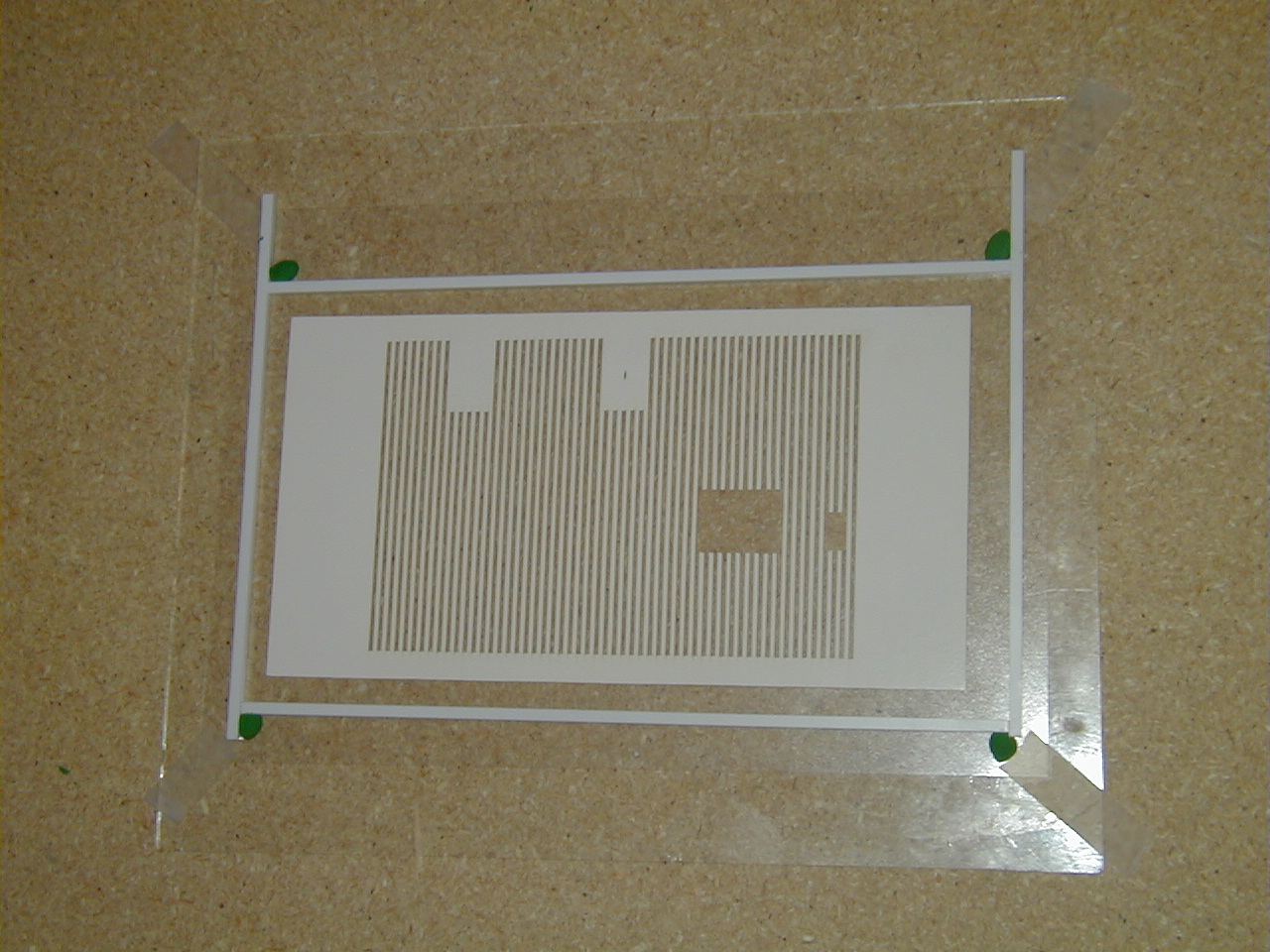 Intertank wrap mold step 1: Half-Pattern (180 degrees) laser-cut by Tom Campbell is carefully laid atop laminating film that is adhesive-side-up (entire set-up is laid atop glass plate, in this case from an 8 x 10 picture frame). Strips of plastic laid along the edges, with clay in corners, to act as mold box for pouring the RTV mold. |
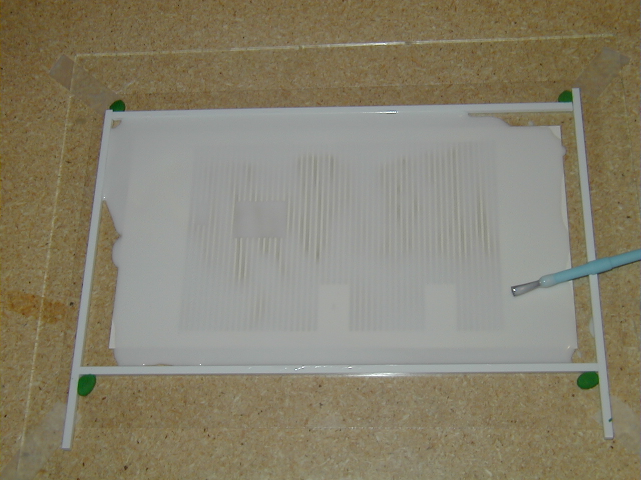 Intertank wrap mold step 2: Carefully brushing RTV into the nooks and crannies of the pattern, careful to prevent voids and air bubbles. |
|
BTW - This 180 degree wrap is for the -Z, or non-orbiter, side of the Intertank |
|
|
|
 ET SRB aft Attach Rods: 1/8" Aluminum rods were machined with half-shaft ends (by Bob Biedron) and 1/32" holes drilled thru to attach 1/32" brass pins. The 1/8" rods were mounted inside of the 5/32" aluminum tubing glued to the aft dome, thin CA was used to secure the 1/8" rods inside the tubing. |
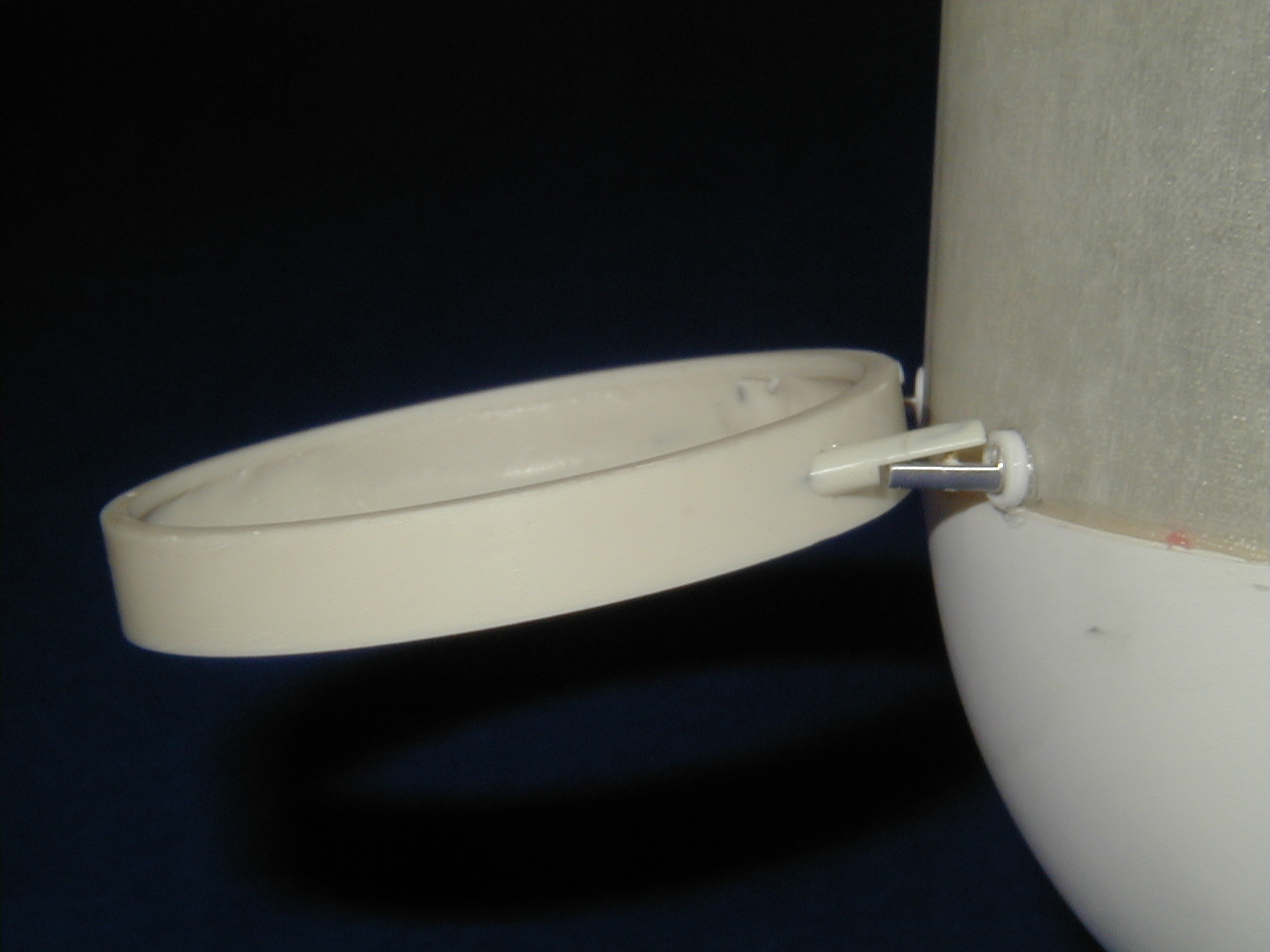
 SRB Aft Attach Ring: Cast ring has 1/32" music wire reinforcement inside of the struts to make them less fragile. 3/64" holes in the half-shaft portions engage the 1/32" pins of the ET SRB attach struts. |
 ET and SRB Ring attached: SRB aft attach ring shown without SRB, for clarity of operation. Note how the half-shaft portions of the struts fit with each other. |
|
|
|  Wedge-Casting: The ET has some "foam ramps" that have a wedge cross-section. Basic wedge shapes were cast as shown, with styrene sheet plastic built up as molds for casting Alumilite wedges. After curing, the wedges were trimmed to the desired width, and further altered to the desired end shapes by sanding. |
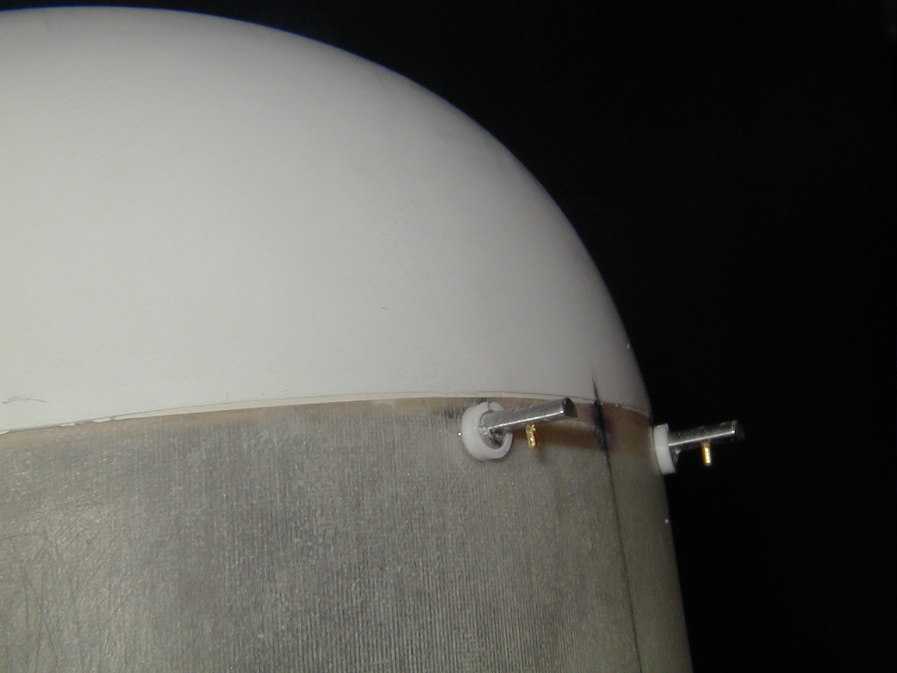
 ET Nose Switches #1: Two lever switches mounted in an assembly so that two small 1/32" pins keep the switches open, until the pins are removed before flight. Shown with one pin in place, holding one of the two switches down. One swithc is from computer power, the other is for arming the ET ejection charges. |  ET Nose Switches #2 View of the other side of the switch assembly. Two small holes are drilled into the ET nose, one above the other, for the Computer power and Ejection Arming switches. |  ET Nose Switch holes: Two holes slightly over 1/16" diameter to allow for the two tubes coming from the ET Nose Switch Assembly. The holes are placed in line with a lengthwise seam, as it is necessary to split the ET nose to get it off of the mold after forming, then glue and splice it back together. The conduits that run down the ET nose are glued over the seam and holes, making the holes almost unnoticeable unless you know to look for them. |
|
| Assembly of NARAM Shuttle |
|
|
|