Back to Shuttlepics

ET - External Tank

Back to Main WSMC CD 


et_1-small.gif


9801795.JPG


et-intertank_1.jpg


pic016_ETassembly.jpg


8217298_STS-3.jpg
ET nose contains Liquid Oxygen.
Corrugated section is the intertank, which actaually has hat-stringers atop a continuous skin.
Cylindrical section aft of the intertank is the Liquid Hydrogen tank

Also see the MSFC photos

Intertank takes the thrust loads from the SRB's. Also supports the Lox tank (nose) on top and pulls on the Hydrogen tank.
ET's are assembled in Michoud, Louisiana.

Same facility originally made first stages for Saturn-I's, IB's, and V's

Photo of STS-3 ET, from the MSFC folder.

ET's are brought in by barge. SRB segments by railroad.


SRB_Nose_Scan.jpg
 
ET_Stack_in_VAB.JPG
 
KSC-96PC-0969_STS-79.jpg
 
Shuttle_ET_Backside.jpg

Columbia_Upnozzle_s.jpg
Either STS-1 or 2. Pipe seen on left side of ET is an anti-geyser line that was deleted a few flights later. Note stringers visible in intertank area near SRB which was filled in by foam on later ET's (until the SLWT's)
Photo from Stack Closeups folder
Not sure of this, but the white conduit line tips off that this may be STS-3's ET.
STS-79 ET
The non-orbiter side of the ET is not seen often. Mission unknown, but may be a recent one since the Intertank access door is black (graphite) , indicating this may be a Super-LightWeight Tank.
Good view of aft details.

Mission not known.

Photo from Stack Closeups Folder


KSC-95PC-0768.jpg
 
GOx%20vent_and_grid.jpg

hailworkerc_STS96_ET_cap.jpg

et-2_NoseConduit.jpg

Partial view of ET nose. The nose has two louvered vents for gaseous oxygen, and a fairing for conduits.
Light yellow holes in foam at left are woodpecker damage.
More below.
Gaseous Oxygen vent. Markings at bottom are a gridline for a TV camera to reference when positioning the pad's "beanie cap" over the nose. The cap has hoses which vent the Gox away from the shuttle stack until a few minutes before liftoff.
More recent Lightweight ET's (since June 1998) use Graphite noses.


Conduit lines that run down from nose tip to intertank.


holes-in-et.jpg


KSC-95PC-0823.jpg
 
ET-37_Nose.jpg
 
ET-37_W_SRBs_plusZ_Jun90.jpg
 
ET-37.jpg
Woodpecker hole damage in insulation.
Repair work on woodpecker holes.

INTERTANK
 
STS-30_INTNK_Door_Umbil.jpg

 
STS-30_INT_Door_Umbil_crop.JPG


STS-31_ET-34.jpg
 
GUCP.jpg

"Far side" of ET, away from orbiter. Left SRB at right.

Access door. More recent Super LightWeight Tanks use a graphite composite door
Gaseous Hydrogen vents thru the umbilical connection plate to a hose. There are also electrical connections. Seen here with a special plug in place over the plate.


STS-36 ET-33 1-90 RSSant.jpg

STS-59_ET-63_Mar94.jpg  


STS-36_GOxpressline_frustum.jpg


STS-36_Feb90_ET-33_BI036.jpg

RSS Antenna (white) on left. Far right, an aerodynamic vent.
Left: Lox line and aerodynamic fairing.
Right, Gaseous Oxygen pressurization line.
Center:Gaseous Oxygen pressurization line & brackets.

Right: SRB Forward Skirt & Frustum

Good view of upper left SRB, intertank of ET, and orbiter nose. Also the umbilical connection to the GUCP.
AFT STRUTS

Also see
Struts & interfaces

 
STS-36 ETAR LH2 detail.jpg

STS-36.jpg

STS-32 ET-32 nov 89.jpg
  
8114209_STS1_SRBsep.jpg

ET/Orbiter & ET/SRB strut details
Fiber optic cable allowedthis view from STS-1 shortly before SRB sep.
Photos from the

STS-47 folder


47INTE-1.JPG
 
47BACK-1.JPG
 
47AFTD-1.JPG

47UMBI-1.JPG

Left: Intertank access door.
Middle: GUCP umbilical
Right: Left hand SRB
View of "far side" of ET.
Closer view, better detail visible of ET aft dome, struts, & SRB attach rings. Also the "manhole covers" used for construction access inside the ET Hydrogen tank before being welded shut.
Right side view of ET aft strut attachment with Orbiter & other details
Three photos of Pathfinder shuttle at US Space & Rocket Center in Huntsville, AL. ET is a non-flight rated prototype that was used for the MPTA static firing tests. Many details NOT applicable to any flown mission. But it can help to get familiar with the basic layout of the key strut components before moving on to detailed views of real ET's


Pathfinder_ET_1..JPG


Pathfinder_ET_2..JPG


Pathfinder_ET_3.j.JPG

Two photos merged
Two photos merged


aftattach.JPG


hydumb.JPG


loxumbil.JPG


challeng.jpg
View of left ET/Orbiter aft attachment, from left and looking towards orbiter belly. Surface of ET to left. Colors of struts have varied somewhat.
Left Umbilical connection with orbiter. At left in background is the Liquid Hydrogen line
Right Umbilical, for Lox line and other connections.Don't know if the transparent red plastic is removed before flight.

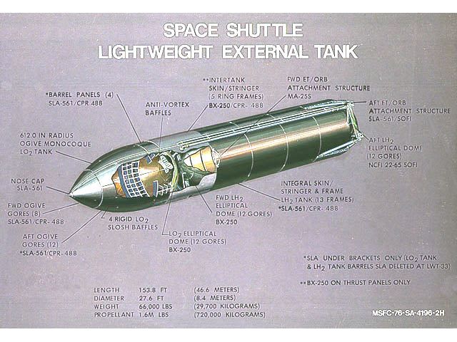
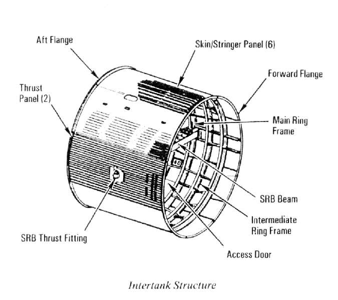
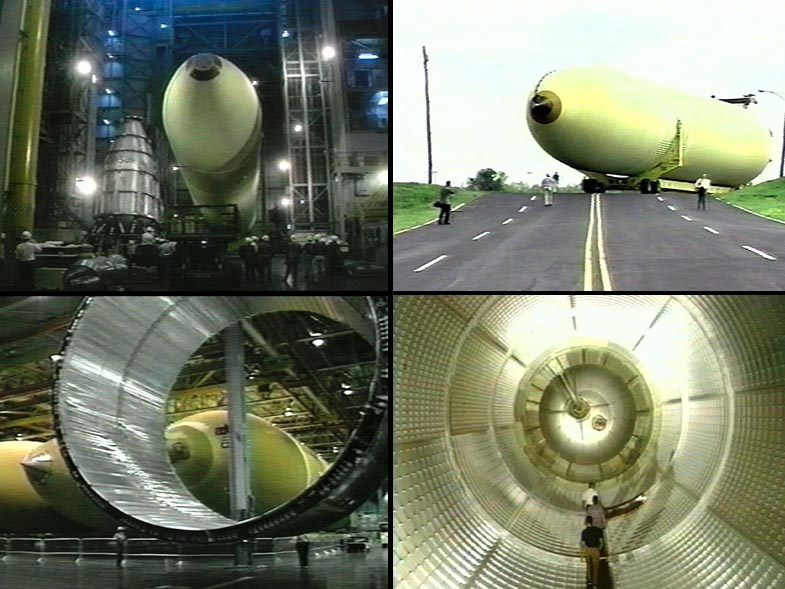
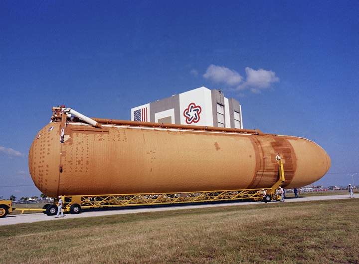
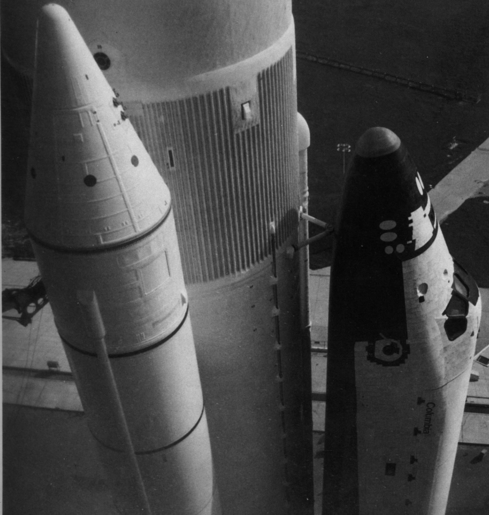
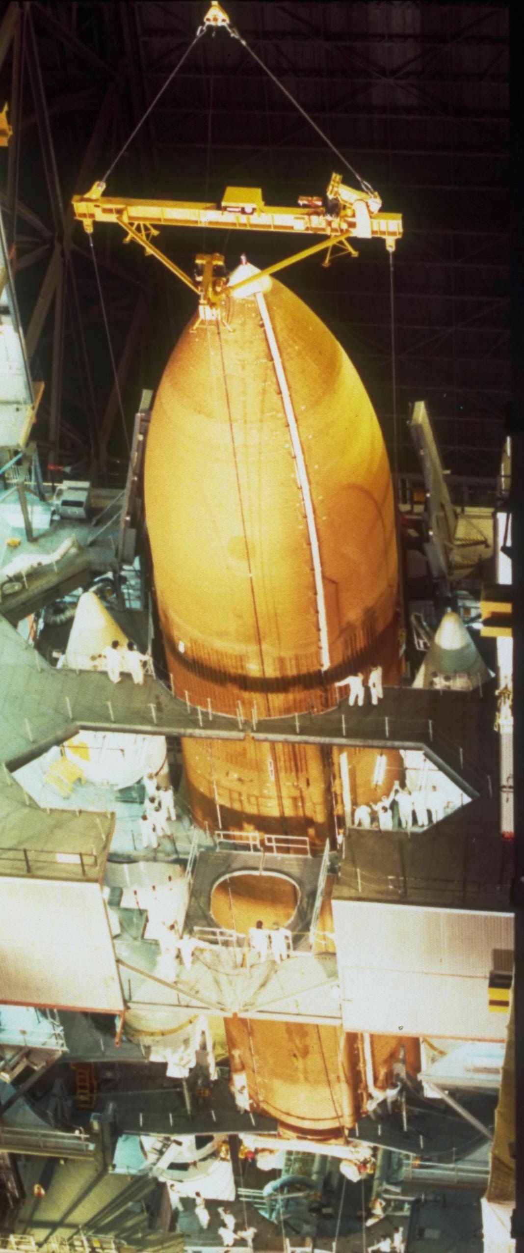
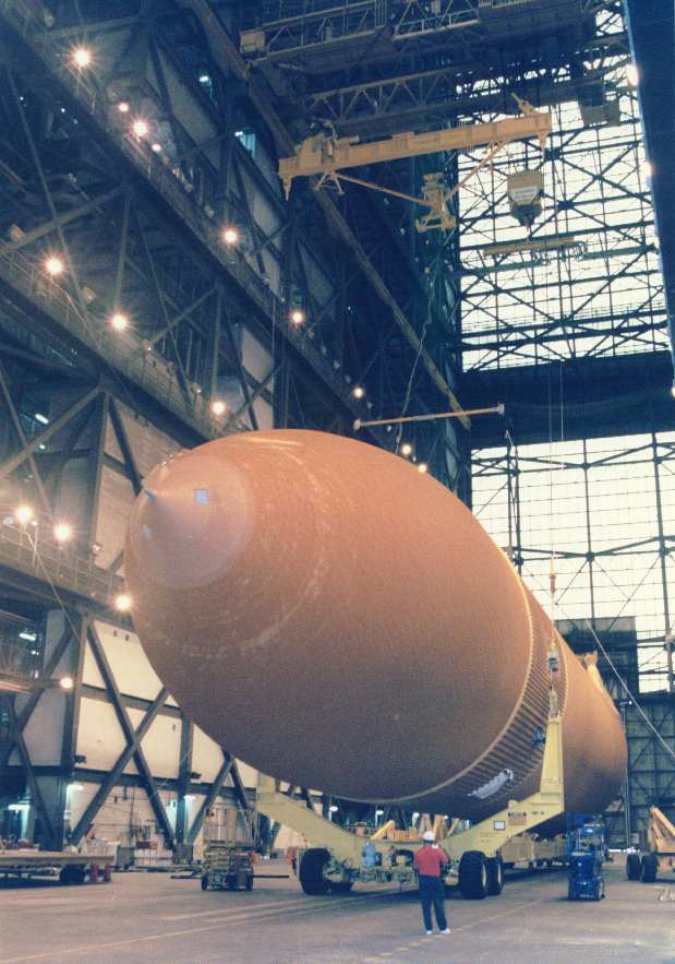
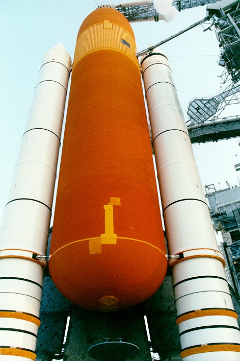
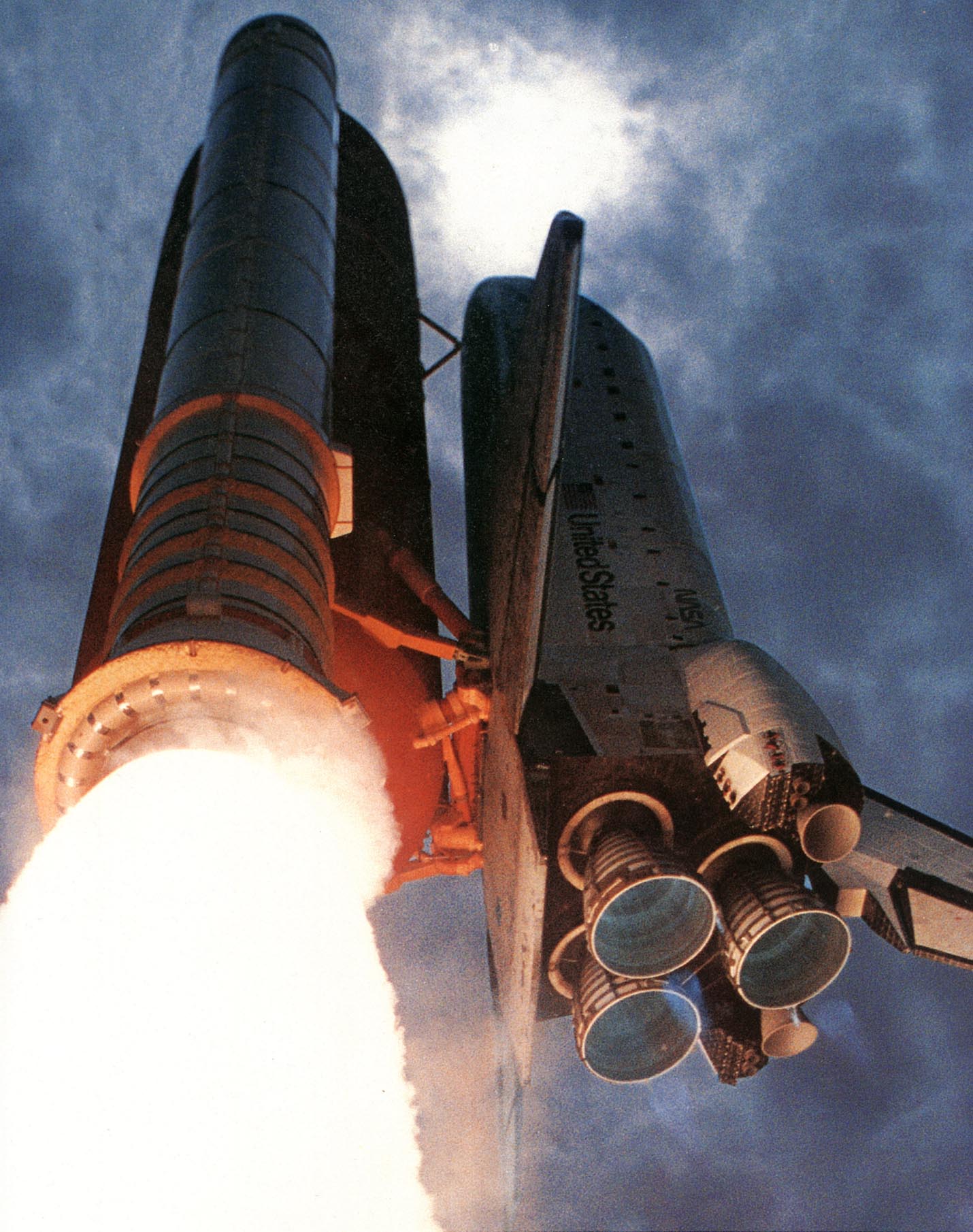
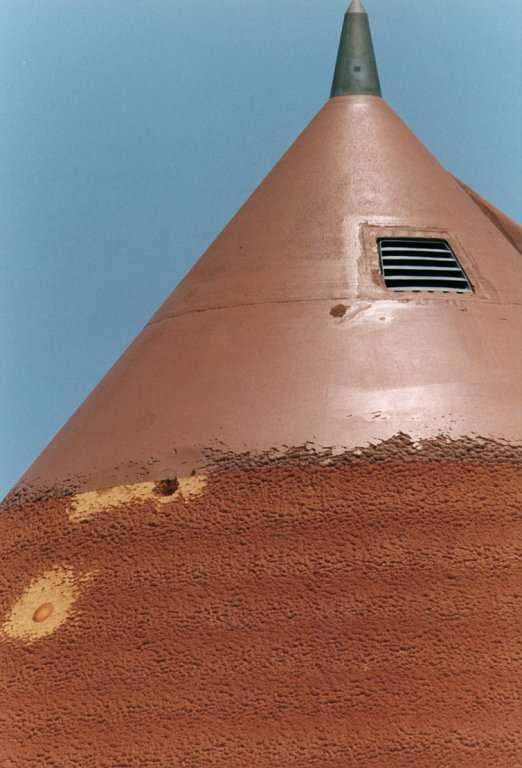
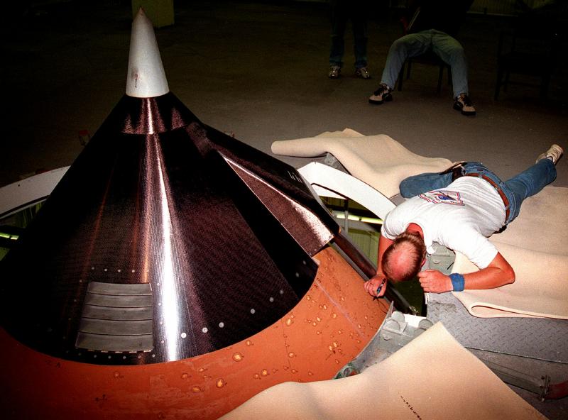
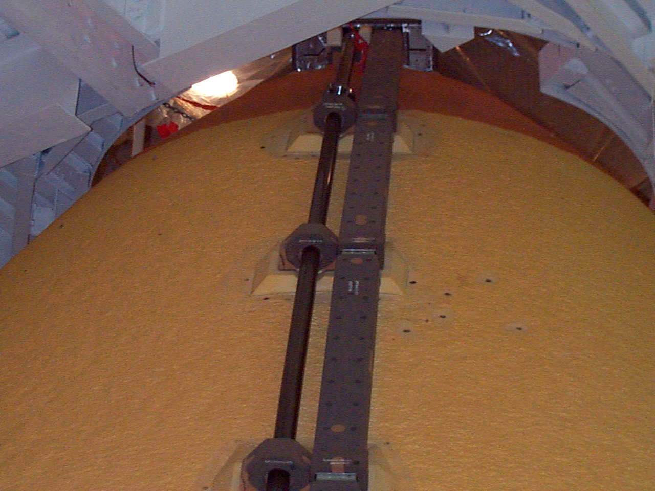
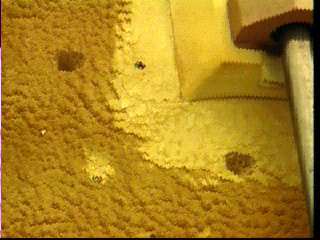
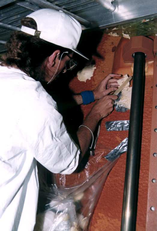
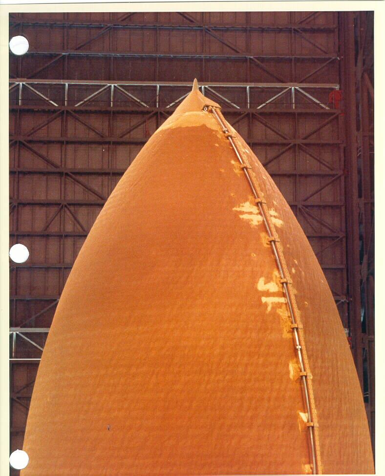
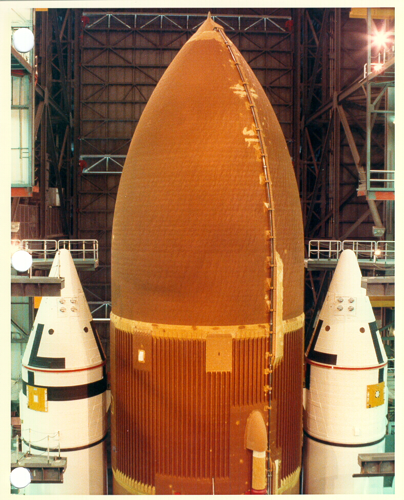
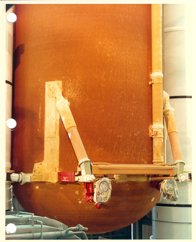
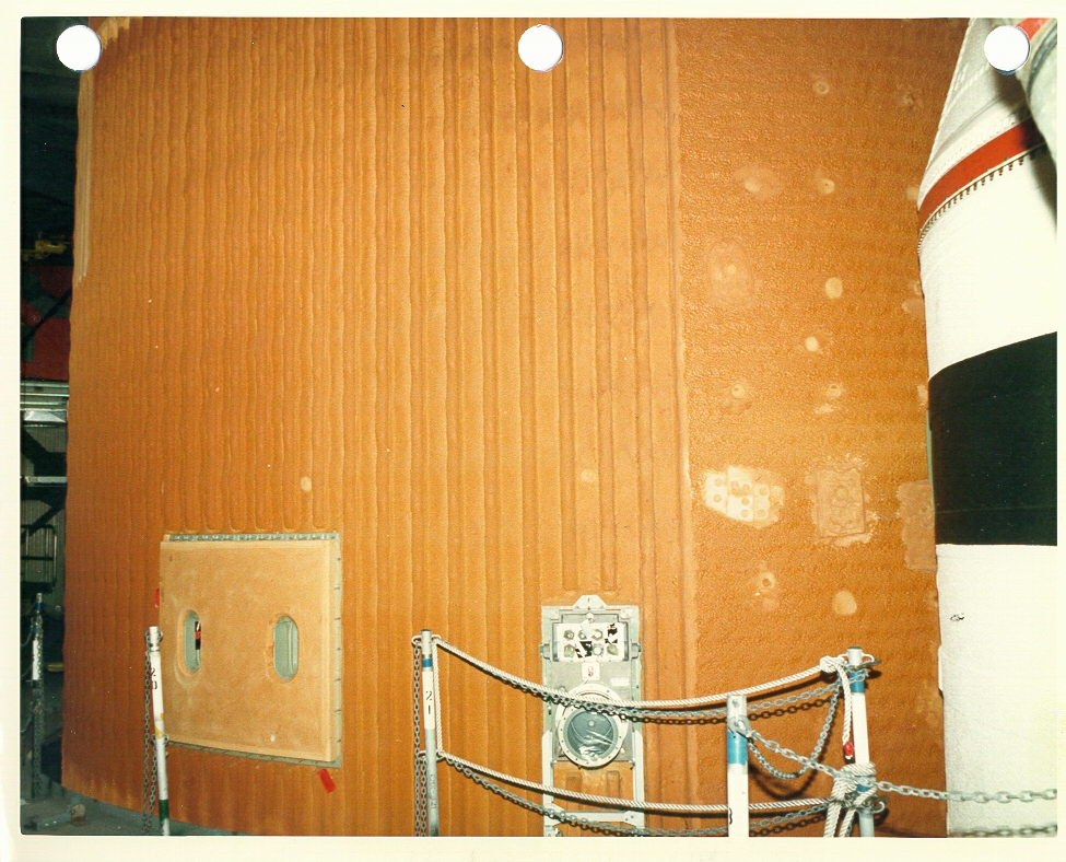
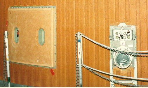
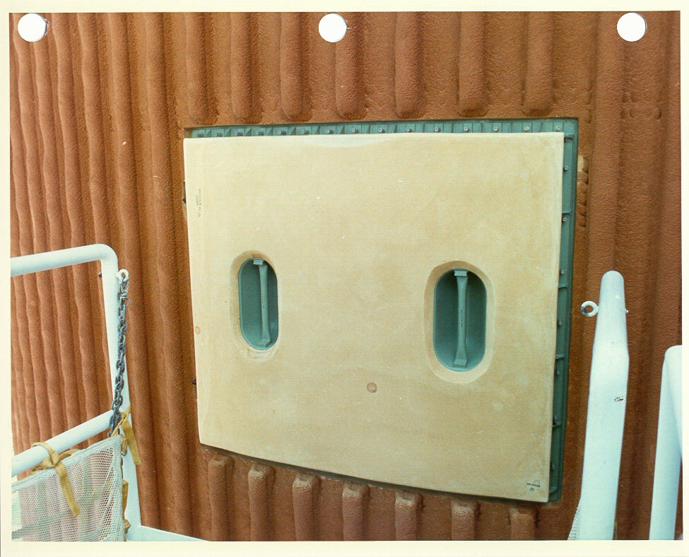
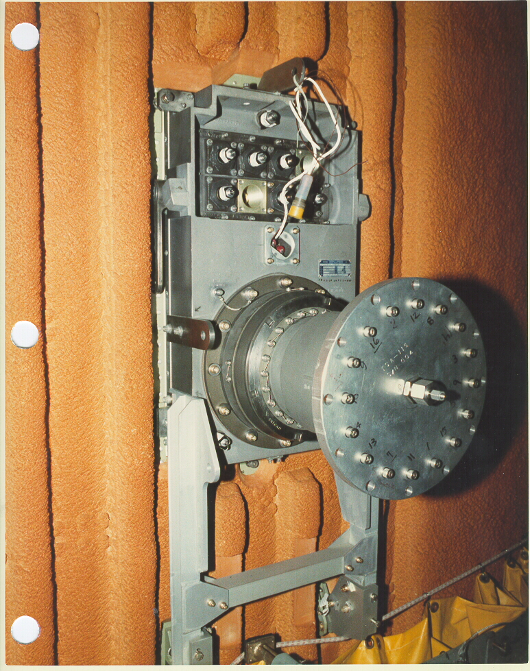
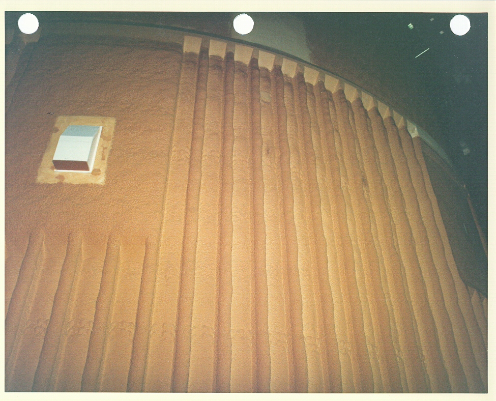
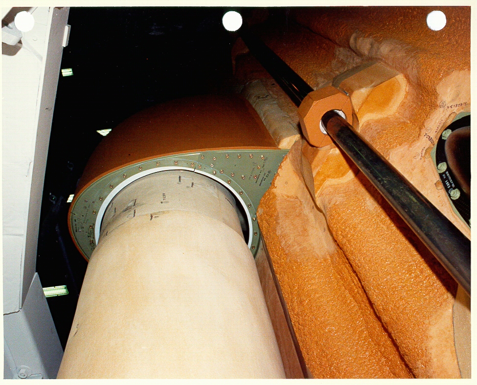
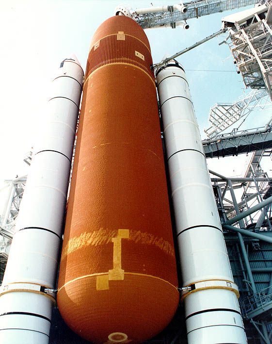
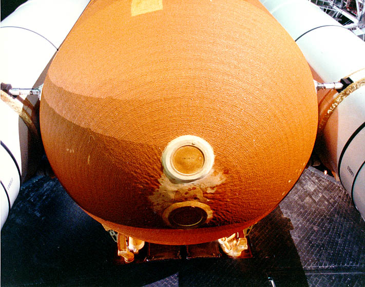
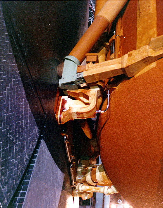
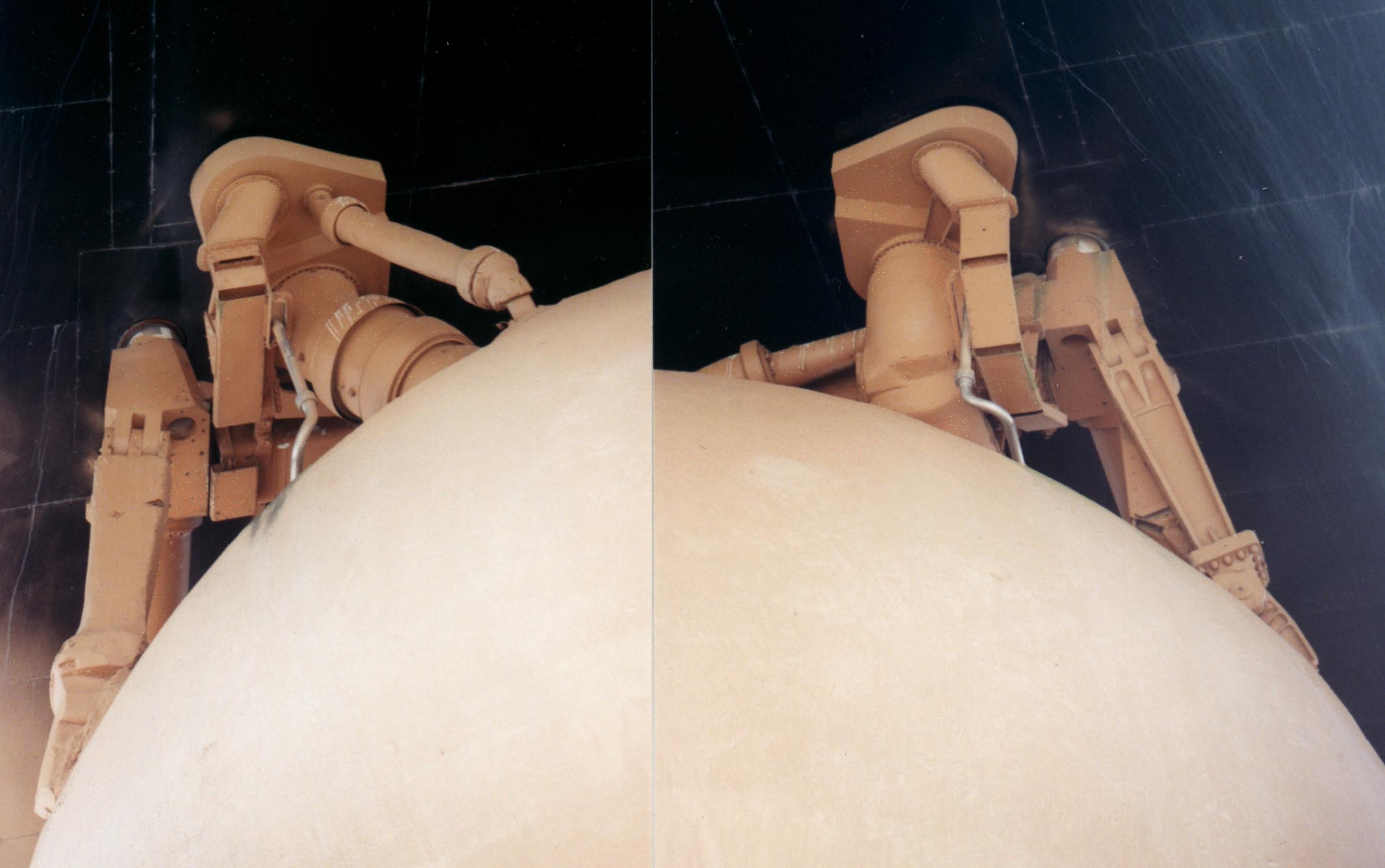
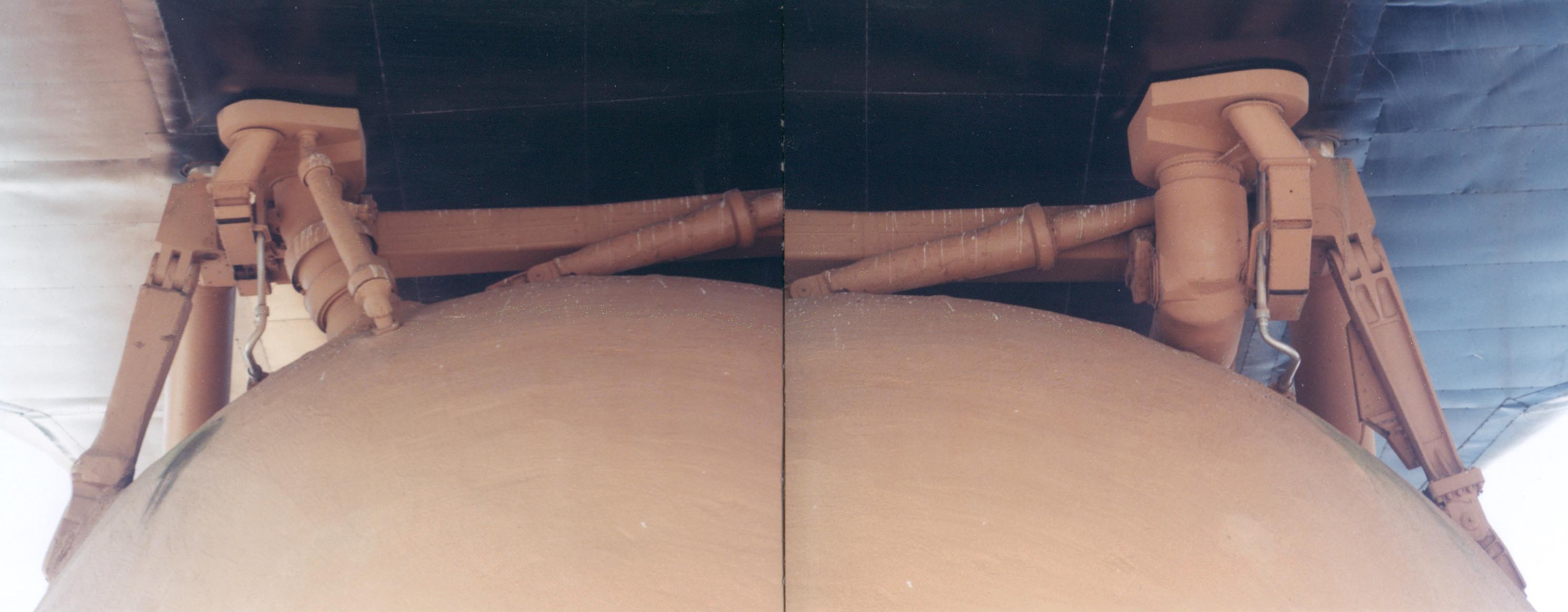
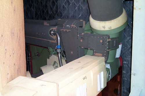
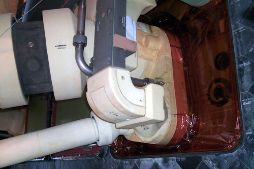
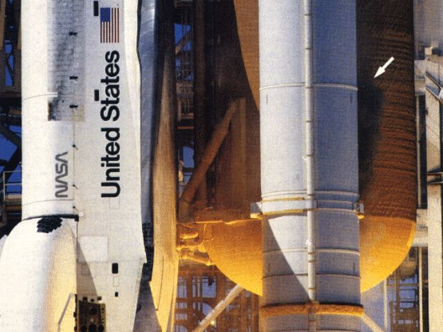
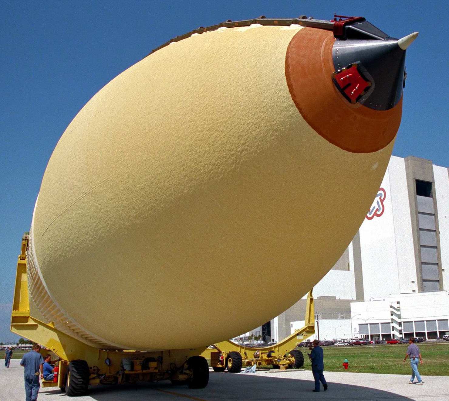
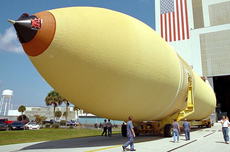
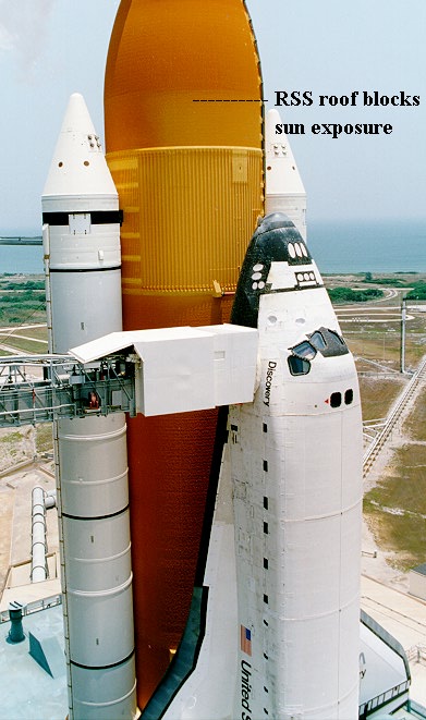
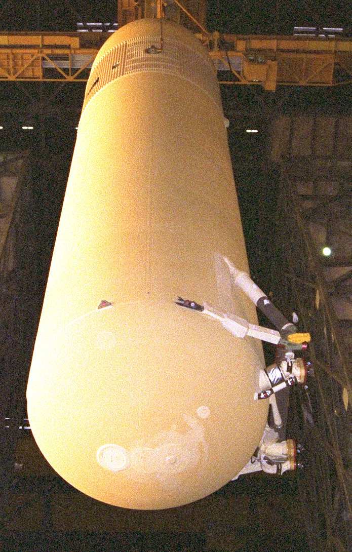
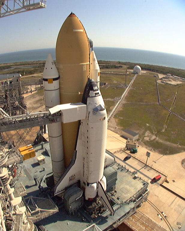
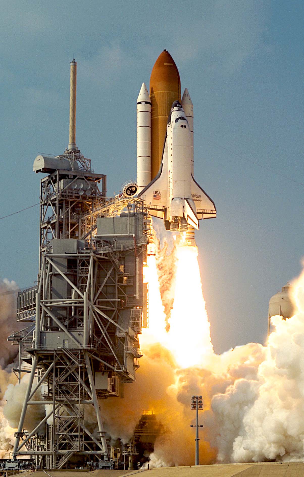
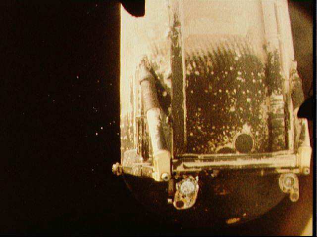
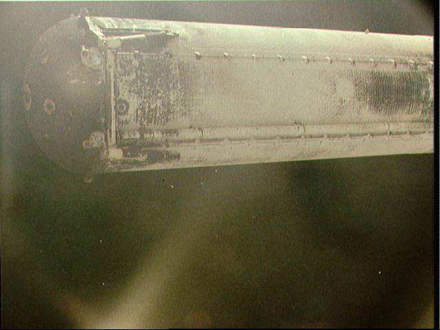
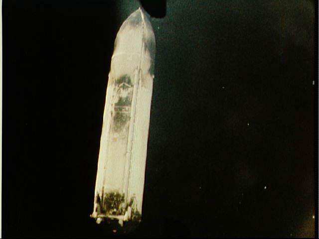
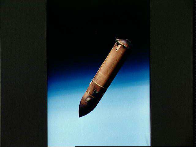
ET differences

The first two ET's were painted white. After that, they have been the natural color of the foam insulation. The color of the foam varies a lot. The foam originally is much lighter in color. Both age, and especially exposure to sunlight, causes it to darken. Due to slips in launch schedules, some ET's sat in storage for a very long time, so they got even darker. Also, in some photographs the color may vary due to the exposure or lighting. The only truly realyl useful color comes from photos on the day of launch and even then it depends on the lighting, exposure, and film color sensitivity.

On tanks that look dark orange or rust, but also have lighter orange or yellow-orange places on them, what is that about? Two causes. One, where new foam was applied in places for various reasons. Such as building up the foam ramps that are along the right sides of the conduit lines. The other, where old foam was ground down or cut into for some reason. Only the outer part gets dark, like a "rind", so when the rind is cut away the exposed old foam is lighter in color.

More recent ET's, "Super Lightweight Tanks", first flown in June 1998, are even lighter. I do not know if the foam itself is any different, or if the ET's are being produced closer to the time of launch rather than being stored for a very long time. In any case, the tanks can have an almost butter-yellow color to them when they arrive, as seen below. When rolled out, they might look a little darker, but not much. The big thing is that being exposed to sunlight for weeks on the pad, the foam gets significantly darker. But the RSS covers a lot of the tank from direct sunlight. So when the RSS is rotated back for launch, the ET has a sort of a "sunburned look", the exposed areas are darker than the areas protected by the RSS.

The SLT's have other differences than color. The ET nose is graphite composite, as is the intertank access door and Lox line fairing. As well, the intertank region shows a webbed stringer pattern that was completely filled-in flight with foam ever since some of the early shuttle flights.But unlike the early ET's there are some horizontal portions that are flush. See the first photo below left for a great view of this.

Second SLWT

(Super Light Weight Tank)

Flown on STS-88


KSC-98PC-0518_LITEET.jpg


KSC-98PC-0517_STS88_LITE_ET.jpg


KSC-98PC-0519_LITE_ET.jpg

Shuttle_LOX_Tank.jpg

STS-88 SLWT
STS-88 SLWT
STS-88 SLWT
Modeler who works at KSC posted this pic to show the sunburn effect. It MIGHT be STS-91 but I do not know for sure.


KSC-98PC-0281_LITE_ET.jpg


KSC-98PC-0282_LITE_ET.jpg


KSC-98PC-0283_LITE_ET.jpg


KSC-98DC-0551_STS91_LITE_ET.jpg


KSC-98PC-0693.jpg

FIRST SLWT, flown on STS-91 in June 1998
Photos on this row are from the STS-91 folder
By the time of launch day, the ET was darker in the areas exposed the most to sunlight.

sts1_1.jpg

sts2_1.jpg

sts1_2.jpg

sts51_1.jpg

sts57_1.jpg
ET's after Orbiter Sep

Only STS-1 and 2 ET's were painted white. The rest have been the natural color of the insulation foam, which varies due to age and sun exposure.

A portion of the SRB exhaust plumes gets recirculated into ET aft dome, causing charring. Aft dome has extra-thick insulation to protect against the heat.
Supersonic aerodynamic heating chars portions of the ET insulation. Particularly under the orbiter nose, orbiter aft section, and intertank SRB region.

Back to Shuttlepics

ET - External Tank

Back to Main WSMC CD 

This pagecreated on a Macintosh using PhotoPage by John A. Vink.