Finned Rocket Design for Stable Boost – Glider Tower & Finned Rocket Systems

The design of finned rockets for boost-glide applications represents a sophisticated engineering challenge that requires balancing the competing demands of aerodynamic stability, structural integrity, and performance optimization. Unlike traditional model rockets that are designed primarily for vertical flight to apogee, boosters for glider applications must maintain stable flight during a horizontal or near-horizontal launch phase before separating to allow glider deployment.
Successful finned rocket design for boost-glide missions requires a deep understanding of aerodynamic principles, structural engineering, and the unique flight characteristics of integrated launch systems. These rockets must generate sufficient thrust and acceleration to achieve the velocity necessary for successful glider transition while maintaining stable flight throughout the boost phase.
Modern finned rockets for boost-glide applications incorporate advanced design features and materials that enable performance levels that were once thought impossible. This evolution has been driven by competitive demands, technological advances, and a growing understanding of the complex aerodynamic interactions that occur during boost-glide flight.
Aerodynamic Stability Principles (Center of Pressure vs. Center of Gravity)
Understanding the fundamental principles of aerodynamic stability is essential for designing effective finned rockets for boost-glide applications. The relationship between center of pressure (CP) and center of gravity (CG) determines whether a rocket will fly stably or experience destabilizing forces that can lead to flight failure.
Center of Pressure Fundamentals
The center of pressure represents the point at which all aerodynamic forces acting on a rocket can be considered to act. For stable flight, the center of pressure must be located aft (behind) the center of gravity. This arrangement creates a restoring moment that tends to align the rocket with its flight path when disturbed.
Center of pressure location varies with flight conditions, particularly Mach number and angle of attack. At low speeds, the center of pressure is typically located near the midpoint of the rocket’s length, but it moves aft as speed increases due to changes in pressure distribution over the vehicle surface.
For boost-glide applications, center of pressure considerations are particularly complex because the rocket experiences a wide range of flight conditions during the boost phase. The design must ensure adequate stability margins across the entire flight envelope from launch to separation.
Maintain a minimum stability margin of one caliber (rocket diameter) throughout the expected flight envelope. For high-performance boost-glide rockets, margins of two or more calibers may be necessary to ensure stable flight under all conditions.
Center of Gravity Considerations
The center of gravity represents the point at which the rocket’s weight can be considered to act. Unlike the center of pressure, the center of gravity remains relatively fixed during flight unless propellant is consumed or components are jettisoned. In boost-glide applications, the center of gravity shift due to propellant consumption must be carefully considered.
Forward weight distribution is critical for maintaining adequate stability margins as propellant is consumed during flight. Placing heavy components such as motors, payloads, or recovery systems forward of the vehicle’s midpoint helps maintain the required CG-to-CP relationship throughout the boost phase.
Weight distribution also affects the rocket’s moment of inertia, which influences its response to control inputs and disturbance forces. Proper weight distribution can improve handling characteristics and reduce the likelihood of oscillatory instabilities.
Dynamic Stability Analysis
Static stability analysis, while important, does not provide a complete picture of rocket stability. Dynamic stability analysis considers the rocket’s response to disturbances over time, including the potential for oscillatory instabilities that can grow rather than decay.
Damping characteristics are critical for preventing oscillatory instabilities that can reduce performance or lead to structural failure. Adequate damping requires appropriate fin size, placement, and configuration to provide sufficient restoring moments without excessive drag penalties.
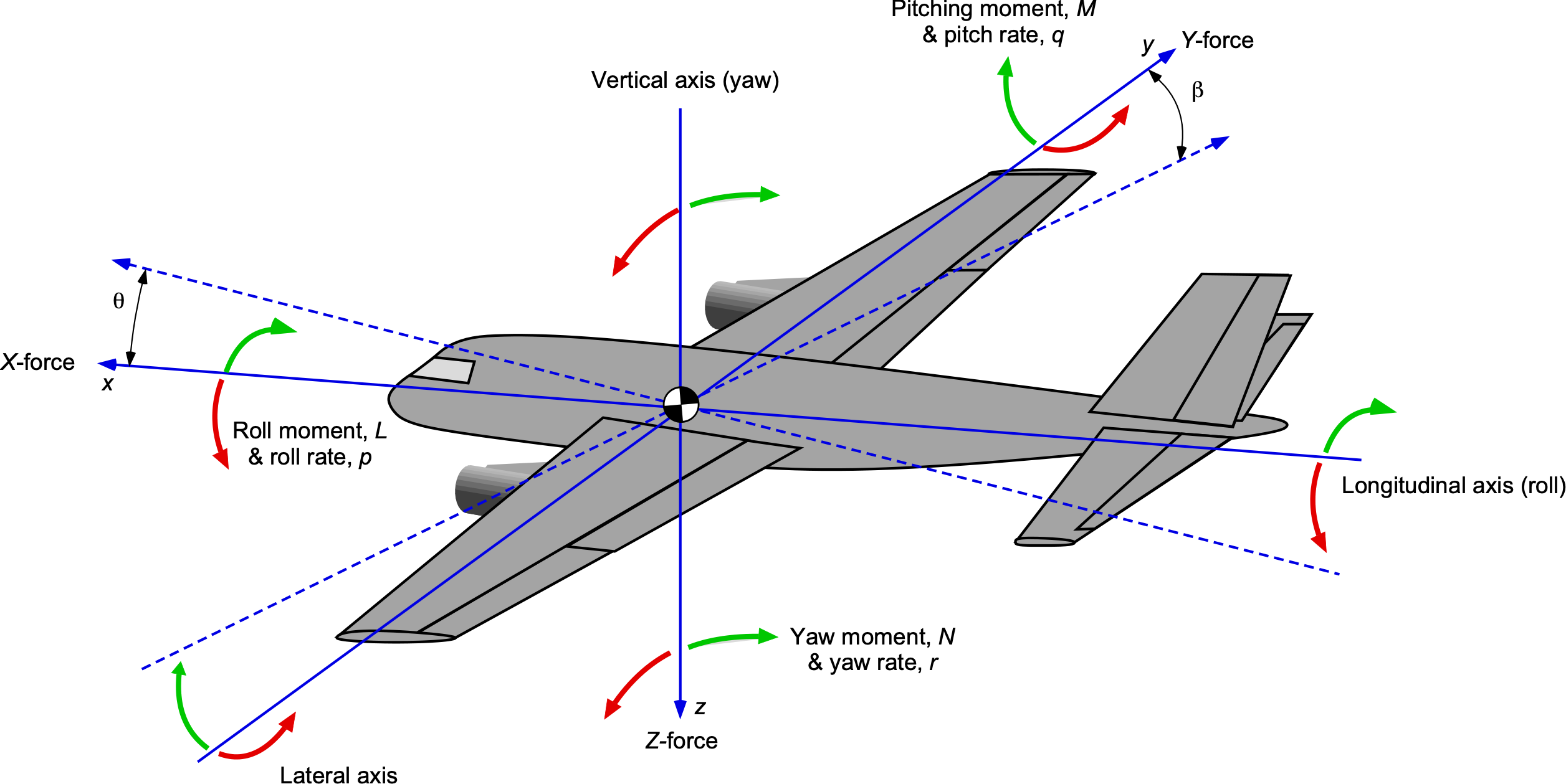
Coupled motion effects such as the interaction between pitch, yaw, and roll motions can significantly affect stability. These effects are particularly important for boost-glide rockets that may experience significant crosswinds or asymmetric loading during launch.
Fin Shape, Size, and Placement for Glider Compatibility
Fin design for boost-glide rockets must consider not only aerodynamic stability but also compatibility with tower launch systems and glider separation requirements. The fins must provide adequate stability while avoiding interference with launch guidance and ensuring clean separation from the glider.
Fin Planform Selection
Fin planform significantly affects both aerodynamic performance and structural characteristics. Common planforms include clipped delta, tapered, and rectangular configurations, each with specific advantages for different applications.
Clipped delta fins offer excellent supersonic performance and structural efficiency while providing good subsonic characteristics. These fins are particularly suitable for high-performance boost-glide rockets that operate at speeds approaching or exceeding Mach 1.
Tapered fins provide a good balance of aerodynamic efficiency and structural characteristics while offering flexibility in center of pressure location. These fins can be optimized for specific flight conditions through variation of taper ratio and sweep angle.
Rectangular fins offer simplicity in design and manufacturing but may be less efficient aerodynamically than tapered configurations. These fins are often used for educational or budget-conscious applications where maximum performance is not critical.
Fin Sizing Methodology
Proper fin sizing requires consideration of multiple factors including stability requirements, drag penalties, and structural constraints. The goal is to provide adequate stability with minimum drag and weight penalties.
Fin area requirements can be estimated using empirical methods based on rocket length, diameter, and expected flight conditions. These methods provide initial sizing estimates that must be refined through detailed analysis or testing.
Aspect ratio selection affects both aerodynamic efficiency and structural characteristics. Higher aspect ratio fins are more aerodynamically efficient but may be more prone to flutter or structural failure under dynamic loads.
Fin size must be compatible with tower launch system constraints. Fins that are too large may interfere with launch guidance or create excessive drag during the initial launch phase, reducing overall system performance.
Fin Placement and Configuration
Fin placement affects both static and dynamic stability characteristics. Fins placed near the vehicle’s aft end provide maximum static stability but may be more susceptible to dynamic instabilities.
Multiple fin configurations such as four or six fins can improve stability and reduce the impact of single-fin damage or manufacturing variations. These configurations also provide redundancy that can improve flight reliability.
Fin canting (angling) can be used to induce controlled spin that improves dynamic stability. This technique is particularly useful for long, slender rockets that might otherwise be prone to oscillatory instabilities.
| Fin Configuration | Advantages | Disadvantages |
|---|---|---|
| Three Fins | Minimum drag, simple manufacturing | Less redundancy, potential for asymmetric failure |
| Four Fins | Good stability, redundancy, common configuration | Slightly higher drag than three fins |
| Six Fins | Maximum redundancy and stability | Higher drag and weight penalties |
Structural Design for Performance and Reliability
Structural design of finned rockets for boost-glide applications must accommodate the demanding load conditions encountered during launch while maintaining the precision required for stable flight. These structures must be both lightweight and strong, representing a classic engineering optimization challenge.
Load Analysis and Distribution
Aerodynamic loads during boost create significant forces on the rocket structure, particularly on fin mounting points and body tube connections. These loads must be accurately calculated and distributed through the structure to prevent failure or excessive deformation.
Dynamic loads from motor ignition, thrust oscillations, and aerodynamic buffeting can create transient conditions that significantly exceed steady-state load estimates. These loads must be considered in structural design to ensure adequate safety margins.
Thermal loads from motor operation and aerodynamic heating can affect material properties and create thermal stresses that must be accommodated in the design. These effects are particularly important for high-performance motors or extended boost phases.
Material Selection and Fabrication
Material selection for rocket fins must balance strength, stiffness, weight, and cost considerations. Common materials include cardboard, balsa wood, plastic, and composite materials, each with specific advantages for different applications.
Cardboard and balsa wood offer low cost and ease of fabrication but may be susceptible to moisture damage and have limited strength. These materials are suitable for educational or low-performance applications.
Plastic materials such as polystyrene or ABS offer improved durability and moisture resistance while maintaining reasonable weight and cost. These materials can be easily formed into complex shapes but may have limited temperature resistance.
Composite materials such as fiberglass or carbon fiber provide exceptional strength-to-weight ratios but at significantly higher cost and complexity. These materials are typically reserved for high-performance applications where maximum performance is critical.
Joint Design and Assembly
Fin-to-body joints represent critical structural connections that must transfer aerodynamic loads while maintaining alignment and allowing for thermal expansion. These joints must be designed for both initial strength and long-term durability.
Adhesive bonding offers excellent load distribution and can provide strong, lightweight joints when properly designed and executed. This method requires careful surface preparation and adhesive selection to ensure adequate strength and durability.
Mechanical fastening through bolts or screws provides positive attachment and allows for disassembly but may create stress concentrations and add weight. These methods are often used in conjunction with adhesive bonding for critical applications.
Hybrid approaches combining multiple attachment methods can optimize performance while providing redundancy. These approaches may use mechanical fasteners for initial positioning and adhesives for load transfer.
Performance Optimization Techniques
Performance optimization for boost-glide rockets involves maximizing acceleration and velocity while maintaining stability and compatibility with launch systems. This optimization requires careful consideration of aerodynamic, propulsion, and structural factors.
Drag Reduction Strategies
Parasitic drag from fins and body surfaces can significantly impact rocket performance, particularly at high speeds. Minimizing drag while maintaining stability requires careful optimization of shape, surface finish, and configuration.
Surface smoothness is critical for minimizing skin friction drag, particularly at high speeds. Proper finishing techniques including sanding, filling, and painting can significantly reduce drag compared to rough or unfinished surfaces.
Fin leading edge design affects both drag and stability characteristics. Sharp leading edges reduce drag but may be more susceptible to damage, while rounded edges offer improved durability at the cost of increased drag.
Weight Optimization
Weight optimization is critical for maximizing rocket performance while maintaining structural integrity. Every gram saved in the rocket structure translates to increased velocity or payload capacity.
Hollow fin construction can significantly reduce weight while maintaining structural stiffness. This approach requires careful design to ensure adequate strength and prevent flutter or other dynamic instabilities.
Selective material usage allows for optimization of strength-to-weight ratios in specific areas of the structure. Heavy, strong materials can be used where loads are highest while lighter materials are used in less critical areas.
Motor Integration and Performance Matching
Motor selection and integration significantly affect overall rocket performance and must be matched to the specific requirements of the boost-glide mission. The motor must provide adequate thrust while fitting within structural and aerodynamic constraints.
Thrust-to-weight ratio optimization ensures that the rocket can accelerate rapidly while maintaining stable flight. This ratio must be balanced against structural limitations and aerodynamic requirements.
Burn time optimization affects both maximum velocity and flight profile characteristics. Shorter burn times can achieve higher peak accelerations but may not provide adequate time for stable flight establishment.
Testing and Validation Methods
Testing and validation are essential for verifying that finned rocket designs meet performance and safety requirements. These procedures should include both analytical verification and physical testing to ensure comprehensive validation of design assumptions.
Computational Analysis Tools
Computational fluid dynamics (CFD) analysis can provide detailed information about aerodynamic characteristics and flow field behavior. This analysis is particularly valuable for optimizing fin shapes and predicting performance at different flight conditions.
Finite element analysis (FEA) helps predict structural behavior under load and can identify potential failure modes before physical testing. This analysis is essential for lightweight designs where structural margins may be minimal.
Six-degree-of-freedom (6DOF) simulation tools can model complete flight trajectories and help optimize design parameters for specific mission requirements. These tools are particularly valuable for boost-glide applications with complex flight profiles.
Physical Testing Protocols
Static testing verifies structural integrity under expected loading conditions and can identify potential failure modes or design weaknesses. This testing should include both positive and negative load cases to ensure comprehensive coverage.
Wind tunnel testing provides direct measurement of aerodynamic characteristics and can validate analytical predictions. This testing is particularly valuable for unconventional fin configurations or complex flow interactions.
Flight testing is the ultimate validation of rocket design but requires careful planning and safety procedures. Initial flight tests should use conservative designs and gradually expand the flight envelope as confidence increases.
Always conduct initial flight tests with appropriate safety margins and recovery systems. Ensure that test flights are conducted in accordance with all applicable safety regulations and guidelines.


Post Comment