System Integration and Pre-Flight – Glider Tower & Finned Rocket Systems
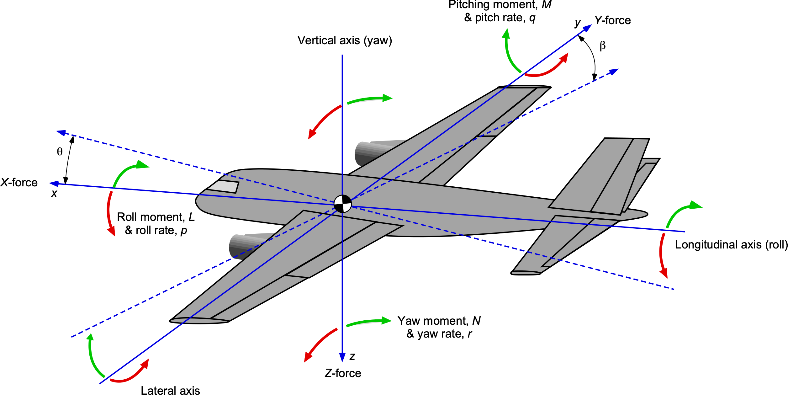
The successful operation of integrated glider tower and finned rocket systems depends on meticulous attention to system integration and comprehensive pre-flight preparation. These complex systems represent the convergence of multiple engineering disciplines, requiring careful coordination of mechanical, aerodynamic, and operational elements to achieve reliable performance.
System integration goes beyond simply connecting components; it involves ensuring that all elements work together harmoniously to achieve the desired flight profile while maintaining safety and reliability. This process requires detailed understanding of each component’s characteristics and the interactions between them.
Pre-flight preparation is equally critical, as even the best-designed system can fail if not properly prepared for flight. This preparation encompasses everything from component inspection and assembly verification to environmental assessment and personnel briefing. Thorough preparation significantly improves the probability of mission success while minimizing risks to personnel and property.
Mating the Rocket to the Glider for Launch
The process of mating the rocket booster to the glider is one of the most critical aspects of system integration, as this connection directly affects both the boost phase performance and the subsequent glider deployment. Proper mating ensures that the combined vehicle maintains stable flight during boost while enabling clean separation for successful glider transition.
Interface Design and Compatibility
Mechanical interface design between rocket and glider must accommodate both the loads experienced during boost and the requirements for clean separation. This interface typically involves a combination of structural connections and release mechanisms that must function reliably under demanding conditions.
Dimensional compatibility ensures that the glider fits properly within the tower guidance system while maintaining adequate clearance for clean separation. This compatibility requires careful coordination between glider design and tower specifications to avoid interference or binding during launch.
Aerodynamic compatibility is essential for maintaining stable flight during the boost phase. The combined vehicle must have appropriate center of gravity and center of pressure relationships, and the interface between rocket and glider should minimize drag and flow separation.
Consider using standardized interface components that can be used across multiple rocket-glider combinations. This standardization reduces development time and cost while improving reliability through proven designs.
Structural Connection Methods
Threaded connections provide simple, reliable attachment between rocket and glider while allowing for easy separation when required. These connections must be designed to withstand boost loads while providing adequate strength for handling and transportation.
Bayonet-style connections offer quick attachment and separation with positive locking features that prevent accidental disconnection during handling. These connections require precise manufacturing tolerances but can provide excellent reliability in field conditions.
Magnetic attachment systems provide non-mechanical connection that can simplify separation but may be susceptible to environmental factors such as metallic debris or temperature effects. These systems require careful design to ensure adequate attachment strength.
Alignment and Positioning
Proper alignment between rocket and glider is essential for maintaining stable flight during boost and ensuring predictable separation behavior. Misalignment can cause asymmetric loading, flight path deviations, or separation difficulties.
Alignment features such as guide pins, alignment marks, or mechanical stops help ensure consistent positioning during assembly. These features should be designed to be easily visible and accessible while providing adequate guidance accuracy.
Centering mechanisms may be necessary to maintain proper positioning of the glider relative to the rocket centerline. These mechanisms can compensate for manufacturing tolerances or assembly variations while maintaining required clearances.
Comprehensive Pre-Launch Checklist
A comprehensive pre-launch checklist is essential for ensuring that all aspects of the integrated system have been properly prepared and verified before flight. This checklist serves as both a memory aid and a quality control tool, helping to prevent oversights that could compromise mission success or safety.
Structural and Mechanical Verification
- Inspect all structural components for damage, cracks, or deformation
- Verify all fasteners are properly tightened to specified torque values
- Check fin attachment points for secure bonding or fastening
- Inspect tower guidance elements for wear, damage, or misalignment
- Verify release mechanism operation and safety features
- Check all hinges, pivots, and moving parts for smooth operation
- Verify center of gravity is within acceptable range
- Check fin alignment and symmetry
- Inspect all surfaces for smoothness and absence of protrusions
- Verify glider attachment does not create aerodynamic interference
- Confirm all control surfaces move freely if applicable
Systems and Electronics Check
- Test all electrical connections for continuity and proper insulation
- Verify battery voltage levels are adequate for system operation
- Test all sensors and indicators for proper operation
- Verify timing circuits and sequencers are properly configured
- Test remote control or telemetry links if applicable
- Confirm all safety interlocks and arming procedures function correctly
- Verify motor installation and retention
- Check propellant expiry dates and storage conditions
- Inspect motor casing for damage or defects
- Verify proper motor delay element selection
- Confirm ejection charge installation if applicable
Environmental and Operational Readiness
- Verify launch site conditions are within acceptable limits
- Check wind speed and direction for compatibility with system limits
- Assess visibility conditions and establish tracking procedures
- Confirm safety zones are properly established and monitored
- Verify communication systems are functioning properly
- Check emergency response equipment and procedures
- Brief all personnel on their roles and responsibilities
- Verify launch authority and clearance procedures
- Confirm recovery team assignments and equipment readiness
- Review emergency procedures and communication protocols
- Ensure all required documentation is complete and current
Integration Testing and Validation
Integration testing validates that all system components work together as intended and identifies potential issues before actual flight operations. This testing should be comprehensive and systematic, covering all aspects of system operation from initial power-up through post-flight recovery.
Ground Testing Procedures
Static integration testing verifies that all components fit together properly and that mechanical interfaces function as intended. This testing should include verification of clearances, alignment, and attachment security without subjecting components to actual flight loads.
Functional testing of all systems ensures that electronic components, sensors, and actuators operate correctly when integrated. This testing should simulate actual flight conditions as closely as possible while maintaining safety.
Load testing verifies that the integrated system can withstand expected flight loads without failure or excessive deformation. This testing may involve applying controlled loads to critical components or using simulation to verify structural adequacy.
Simulation and Modeling Validation
Computer simulations can predict integrated system behavior and help identify potential issues before physical testing. These simulations should include all relevant physics and be validated against test data where possible.
Flight envelope analysis determines the range of conditions under which the integrated system can operate safely and effectively. This analysis should consider factors such as speed, altitude, temperature, and dynamic pressure.
Failure mode analysis identifies potential failure points in the integrated system and helps develop mitigation strategies. This analysis should consider both individual component failures and system-level interactions.
Never proceed with flight operations if integration testing reveals unresolved issues or if any component of the system has not been properly validated. Taking shortcuts in testing procedures creates unacceptable risks to personnel and property.
Launch Sequence Coordination
Successful launch of integrated glider tower and rocket systems requires precise coordination of all elements in the launch sequence. This coordination ensures that each component functions at the proper time and that the overall mission proceeds according to plan.
Timing and Synchronization
Launch timing must account for all system elements, from initial power-up through motor ignition and glider separation. Each step in the sequence must be properly timed to ensure optimal performance and safety.
Synchronization between tower release mechanisms and rocket motor ignition is critical for successful boost phase performance. This synchronization may involve electronic controls, mechanical linkages, or manual coordination depending on system design.
Recovery system timing must be coordinated with boost phase completion to ensure proper deployment after glider separation. This coordination may involve altimeters, timers, or other sensing mechanisms.
Communication and Control
Communication protocols ensure that all personnel are aware of system status and can respond appropriately to changing conditions. These protocols should include clear signals for critical events such as system arming, launch countdown, and emergency procedures.
Control system redundancy provides backup protection against component failures or communication disruptions. Critical functions should have multiple control paths to ensure continued operation even if primary systems fail.
Data recording captures information about system performance and any anomalies encountered during operations. This information is valuable for identifying trends, planning maintenance, and improving future operations.
Post-Integration Verification
Final verification procedures ensure that the integrated system is ready for flight and that all preparation activities have been completed successfully. These procedures provide a final opportunity to identify and correct any issues before launch.
Final Inspection and Sign-Off
Final inspection procedures verify that all components are properly installed and that no damage occurred during final preparation activities. This inspection should be conducted by qualified personnel and documented for future reference.
Sign-off procedures ensure that all required checks have been completed and that the system is cleared for launch operations. These procedures should require authorization from qualified personnel and may include multiple levels of verification for complex systems.
Documentation of pre-launch activities provides a record of system readiness and accountability for verification procedures. This documentation should include the date and time of checks, personnel performing verification, and any issues identified and corrected.
Emergency and Contingency Planning
Emergency procedures must be established and communicated to all personnel before launch operations begin. These procedures should address potential failures of any system component and provide clear guidance for safe response.
Contingency planning addresses potential deviations from normal flight profiles and provides alternative approaches for mission completion. This planning should consider factors such as off-nominal separation events or recovery system malfunctions.
Post-flight evaluation procedures ensure that all system components are properly recovered and that flight data is collected for analysis. This evaluation provides valuable feedback for future missions and helps identify potential areas for improvement.
Conduct a final team briefing immediately before launch to review all procedures, confirm personnel assignments, and address any last-minute concerns. This briefing helps ensure that everyone is prepared and focused for the upcoming flight.


Post Comment